O2 sensor simulator
Last Updated on November 28, 2023 by Mutiara
OBD-II cars (1996 – present) have the two O2 sensors to measure the amount of oxygen in the exhaust gas. First sensor is measuring it right after gases escape engine and this data is used to adjust fuel trim of the engine, as well as catch some faulty conditions. The second sensor is located after the catalic converter, and is used to detect the health of catalic converter, it does not influence the car’s performance in any way. The ECU expects the signal from the sensor to be oscillating from below 0.4v to above 0.6v, but not above 1.2v, every few seconds when cruising.
If the exhaust system is modified to eliminate the catalytic converter the ECU will detect this and throw a code, turning on the check engine light on the instrument cluster. The ECU usually takes a while to detect and report this condition. The ECU can be reset and the error code can be cleared but it’s not convenient and hinders one’s ability to know if there are any other error codes due to a constantly illuminated check engine light.
It is possible to simulate the O2 sensor to eliminate the check engine light. There are two methods to doing this, one is a simpler circuit that creates a load and uses a capacitor to simulate the o2 sensor, while much easier to construct, results may vary. The second more complex circuit is claser to the signal of an o2 sensor and should be used if one has the resources to build it.
O2 sensor simulator circuit #1
The following circuit is very easy to construct. The capacitor and the 1Mohm resistor should be soldered together in parallel. Then the old o2 sensor should be cut off, leaving the plug and wires in tact. After stripping the wires, the capacitor and resistor should be soldered between the blue and white wires, or whichever wires are responsible for the sensor itself. After that the whole thing should be taped or have heatshrink tubing placed on it to avoid any shorts. The other pair, which is for the heater element should be soldered to a resistor of ~ 12 Ohms to create a load, if there is no load on the heater element wires and they are left alone, the ECU will create an error code.
IMPORTANT: Use resistors that are rated for 12 watts of current or use many in parallel. The resistors will get extremely hot and if not rated for the current could start a car fire. Heatsinks can also be used to help.
O2 sensor simulator circuit #2
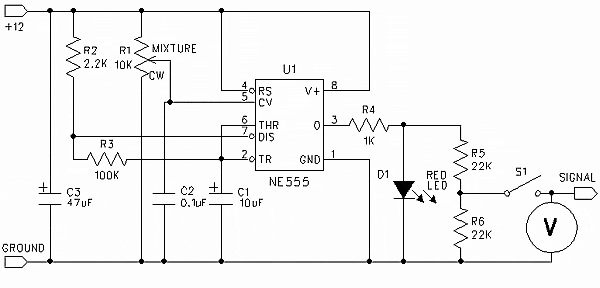
Building the following circuit will provide an oscillating signal generator with just the right frequency and voltage to fool the ECU. It is based on classical stable operating mode of 555 timer. The parts usually cost about $ 15 – $ 20 at RadioShack, however going to a local mom and pop electronics shop will make the project far cheaper. Some RadioShack stores are discontinuing carrying any electronic components.
Components:
- R1 100 K Ohm
- R2 1 M Ohm
- R3 100 K Ohm
- R4 10 K Ohm
- C1 4.7 uF
- C2 22 uF
- D1 1.7v@20mA LED
- D2 1.7v@20mA LED
Hookup:
- Power source – Ignition, or to the ECU PIN #1
- Ground – One of the ground points or ECU PIN #80
- OUT – ECU PIN #47 (disconnect the O2 sensor wire)
RadioShack part numbers:
- 276-309 – 5mm wide angle red led 1.7v, 20mA
- 276-1723 – The 555 programmable timer
- 276-1995A – The 8 pin socket for timer chip. It makes soldering safer and replacement easier
- 276-150A – Generic PC board
- 64-3052A – Pack of blue tap-in connectors
- 278-1225 – Stranded wires (black, red and green)
- 270-1801 – Small black plastic project box 3 x 2 x 1
- 272-1024 – Capacitor, 4.7uF
- 272-1026 – Capacitor, 22uF
Additional notes
If you use different flavors of 555 timer chip or LEDs with different parameters you will need to readjust the values of R4 and R2 to get the interval and output voltage right.
Don’t attach it directly to the ECU right after assembly. Instead attach it to the battery and check the output. You should get approximately 0v/0.7v flipping about every 3.3 seconds when the car is not running, and 0v/0.9v when the car is running. The current should stay below 10mA.
One LED should be always on whenever the power is supplied. Another LED indicates when the output signal is high, so it should go on and off with the signal.
When tapping the ECU wires, triple check everything before hooking up the oscillator. The power source should read 0v when the key is removed, about 12.6v when they key is at ACC and about 14.3 when the alternator is running. The resistance between ground wire and the body shield of the ECU should be 0 ohms. And it would be best if you run the car and monitor the voltage of the original oxygen sensor wire before cutting it to make sure you have indeed got the right one. The resistance between ECU PIN #47 and ground is about 1.3 to 1.6 M Ohm.
The original sensor should still be dangling around, or plugged into the downpipe. The reason is that ECU also monitors the resistance of heater circuit inside the sensor. If you want to COMPELTELY disconnect it, you will need to measure the resistance of the heater circuit and install the right resistor between ECU PIN #72 and ECU PIN #31 Anyway, there is no need to do it if you just leave O2 sensor alone and only intercept the oxygen signal wire.
Above testing and precautions will prevent the ECU from getting fried.


